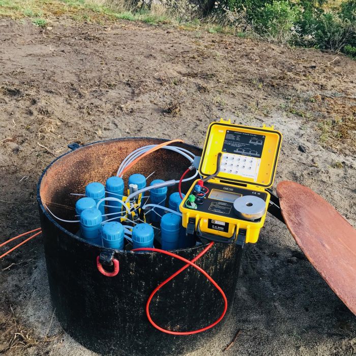
Permanent Electrode Cables System
The Permanent Electrode Cables System is a measuring system to define the amount of salt in the subsoil.
Summary description technique
A subsurface monitoring device is used to measure the electrical soil resistance. Often a Permanent Electrode Cables System (PEC) is used. This is a cable with 13 pairs of electrodes. The PEC is placed permanently (usually vertically) in the soil. The electrode pairs are connected at ground level to a resistance meter. This generates an electrical voltage between two electrodes and measures the potential difference between two other electrodes. This measurement is carried out a number of times, each time with a different combination of electrodes. The measured potential difference says something about the soil resistance at different distances around the used electrodes. Because the subsurface monitoring device is permanently present in the soil, the measurement can easily be repeated later. In this way any changes in soil resistance can be measured easily and quickly. These changes are usually caused by changes in the soil water composition.
Specific information
| General information | |
| Name | Salt Keeper (also known as PEC system). |
| Unit of measure and parameter | Apparent soil resistance in Ohm-meter (or soil conductivity in mS/m). |
| Soil phase | Ground, groundwater and pure product |
| Nature technique | Physical, Geophysical, Probe/sensor |
| Place of application | in situ |
| Applicable in separate layers | Minimum layer thickness: See technical specifications |
| Soil types for which technology is suitable |
|
| Land soil/water bottom | Land soil |
| Step in the data collection chain |
|
| Moment of availability results | Requires post-processing / interpretation off site |
| Technology development phase | widening phase |
| Method of purchasing | As a device |
| General description of the implementation method | A cable with thirteen electrode pairs attached to it is usually placed vertically in the ground. The mutual distance between the electrode pairs is typically 5 meters. A resistance profile can be obtained at any desired time with the salt guard. In this way the electrical soil resistance around the observation well can be monitored. The result of these measurements is a 2D model of the apparent resistance of the subsurface and its changes over time. If the measurements show that a better conductivity occurs over time, this can be an indication of the influx of contaminants or saline groundwater, provided the soil structure remains the same. Another monitoring is possible by means of (permanent) cross-hole resistance measurements. |
| Working principle | The current generated between the two current electrodes creates a difference between the two potential electrodes. The resulting potential difference depends on the local conductivity of the soil, including groundwater with the (polluting) substances dissolved therein. The measured soil resistance is an 'apparent' resistance because not only the soil, but also the matrix and dissolved substances partly determine the measured resistance. The measured values can be used to make a model of the local subsoil in which different layers with different resistance can be distinguished. The method cannot distinguish between layers with equal resistance but different soil structure (clay or contaminants in groundwater). The differences in resistance are especially important for the salt keeper in order to demonstrate differences in groundwater composition (monitoring movement of plumes or fresh/salt boundary). |
| Point / line measurement / volume measurement | Line measurement (vertical) |
Technical specifications (including accuracy) | The measured value of the measurements is within 1% of the actual apparent resistance of the substrate. The changes in apparent resistance over time can thus be accurately monitored. As the distance between the electrodes increases, more information about the bottom at a greater distance from the electrodes is obtained, but the distinguishing power between differences becomes smaller. |
| Typical depth range | Dependent on depth of observation well, Sensitivity independent of depth |
| Time properties | Measurements are performed in an observation well and can be repeated. The results are equivalent with unchanged soil compositions. The salt keeper is ideally suited for monitoring. |
| Measuring rate | The instrument is permanently placed. Measurements can be performed at any time. Measuring at a measuring point takes approximately half an hour. |
| Presentation results | 1D- Electrical resistance models of the subsoil (layer model of the soil with a different electrical soil resistance per layer). Also changes in electrical resistance as a function of time can be indicated. |
| Cost | Purchase equipment costs: Approximately € 10,000 excluding installation costs and the costs of performing measurements and analyzing the data. |
| User information | |
| availabilty | only available abroad |
| Is technology often used? | Incidental |
| Research phase in which technology can be applied | monitoring |
| Verification measurements / calibration measurements | are often applied |
| Frequently used application in practice | Monitoring of pollution plume from landfill. |
| Suitability | The method is especially suitable as a monitoring tool for the spread of contaminants, etc The contaminants that must be monitored must have a measurable effect on the electrical resistance of the groundwater. Macro parameters are pre-eminently measurable parameters, while hydrocarbons, for example, are less measurable. |
| Practical experiences in the Netherlands | The technique has mainly been used at former landfill sites. |
| “Dos“ |
|
| “Don'ts” | |
| Also suitable for | Monitoring of the interface between salt and fresh groundwater. |
References
- Technische Commissie Bodembescherming
- Wikipedia (exploration geophysics)
- TNO
- Design Projects
- COB: Geofysische methoden
